
Introduction to the Raspi GPIO
This article focuses on the Raspberry Pi’s with the 40 pin GPIO connector.
In addition to the familiar USB, Ethernet and HDMI ports, the Raspberry Pi offers the ability to connect directly to a variety of electronic devices.
These include:
- Digital outputs: turn lights, motors, or other devices on or off.
- Digital inputs: read an on or off state from a button, switch, or other sensor.
- Communication with chips or modules using low-level serial protocols: SPI, I²C, or UART. 1-Wire bus can easily be implemented in software using any io pin.
- Analog inputs/outputs:
No analog input or output is available. However, add-on “HAT” boards such as the “ADC PiZero”, “ADC-DAC PiZero”, “Automation HAT” etc. provide this capability or you could add an ADC/DAC board yourself. - PWM outputs: 2 pins can be programmed to output PWM pulses. PWM is useful when you want to dim a LED or make a poor man’s Digital to Analog Converter (DAC).
On the Raspberry Pi’s with the 40 pin connector, 28 of the pins are available as GPIO. (Although 2 are reserved for the HAT I2C interface, but can be used as normal GPIOs if not using a HAT board) The rest is power and ground pins. (Previous versions of the Pi had an IO connector with 26 pins; 17 of them could be used as IO, plus 4 more on the P5 connector on a Revision 2 Pi)
The following Raspberry Pi models have the 40 pin connector available on the circuit board:
- Raspberry Pi Zero
- Raspberry Pi Zero W
- Raspberry Pi Model A+
- Raspberry Pi Model B+
- Raspberry Pi 2 Model B
- Raspberry Pi 3 Model B

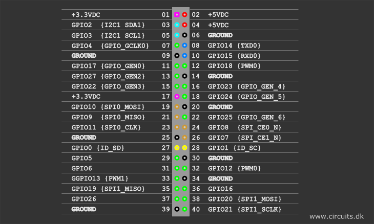
So what do these pin numbers and names mean?
“GPIOxx” is referred to the Broadcom chip pin number usually referred to as “BCM” number. These are the ones you probably will use with RPi.GPIO and Pigpio libraries.
The pin numbers of Fig.1. next to the pin is the actual physical pin number on the 40 pin connector.
There is possible to execute the gpio readall command to view a detailed GPIO layout diagram by typing the following in a terminal window:
gpio readall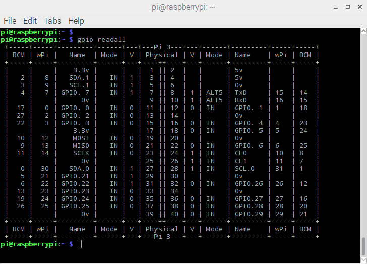
USB 5V input current consumption on different Raspi models
(The data is gathered from rasberrypi.org promotional datasheet, so take this “as is”.)
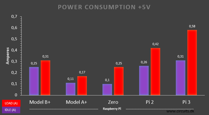
The measurements are of course done with nothing connected to the GPIO port.
Power pins information
The total maximum recommended current draw from the two 3.3 V power output pins is 50 mA.
Maximum recommended current draw from the 5 V pin is the USB input current (usually 1 A) minus any current draw from the rest of the board.
- Model A: 1000 mA – 500 mA -> max current draw: 500 mA
- Model B: 1000 mA – 700 mA -> max current draw: 300 mA
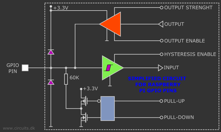
GPIO output current and input voltage recommendations
You should be aware of the following limitations when using the GPIO pins:
- All GPIOs revert to general-purpose inputs on power-on reset.
- These are CMOS 3.3V logic pins and are not 5V logic tolerant. A voltage close to 3.3 V is interpreted as a logic one while a voltage close to 0V is a logic zero.
- There is no over-voltage protection on the board – the intention is that people interested in serious interfacing will use an external board with buffers, level conversion and analog I/O rather than soldering directly onto the main board.
- A GPIO pin should never be connected to a voltage source greater than 3.3V or less than 0V, as prompt damage to the chip may occur as the input pin substrate diodes26) conduct. There may be times when you may need to connect them to out-of-range voltages – in those cases the input pin current must be limited by an external resistor to a value that prevents harm to the chip. I recommend that you never source or sink more than 0.5 mA into an input pin.
- To prevent excessive power dissipation in the chip, you should not source/sink more current from the pin than its programmed limit. So, if you have set the current capability to 2 mA, do not draw more than 2 mA from the pin.
- Never demand that any output pin source or sink more than 16 mA.
- Current sourced by the outputs is drawn from the 3.3 V supplies, which can supply only 50 mA maximum. Consequently, the maximum you can source from all the GPIO outputs simultaneously is less than 50 mA. You may be able to draw transient currents beyond that limit as they are drawn from the bypass capacitors on the 3.3 V rail, but don’t push the envelope!
- There isn’t a similar limitation on sink current. For sink current, the pertinent limitation is that imposed by maximum chip power dissipation. Even so, you can safely sink up to 16 mA each into any number of GPIO pins simultaneously. In the worst case, the output pins (if configured to the 16mA high current drive capability) have a maximum output low voltage of about 0.4 V27), and their internal circuitry dissipates only 6.4 mW worst case. Even sinking 16 mA into 16 pins simultaneously would produce only 0.1024 W, that is, about a tenth of a watt. However, depending on the source of the current, transient sink currents may make demands on the board’s bypass capacitors, so you may not want to switch all the outputs to sink the maximum current synchronously, if you require fast, clean transitions.
- Do not drive capacitive loads. Do not place a capacitive load directly across the pin. Limit current into any capacitive load to a maximum transient current of 16 mA. For example, if you use a low pass filter on an output pin, you must provide a series resistance of at least 3.3V/16mA = 200 Ω.
- The Linux kernel is not suitable for real time applications – it is a multitasking O/S and another process may be given priority over the CPU, causing jitter in your program. If you are after true real-time performance and predictability, buy yourself an Arduino http://www.arduino.cc ! Or make an add-on board with a small microcontroller which handles time critical code and let the RPi handle what it does best; ethernet connection, user interface, usb, bluetooth connection, WiFi, etc.
- If you need fast execution of your IO program use the C programming language. For example, if you just want to flash a few LEDs or read a temperature sensor in a human time scale then you can write in almost any language. However, if you want to directly interface with other systems and control externally connected hardware at its full speed then C is your best choice. Similarly, if timing is critical, then C is the only way to go. Python have too much overhead, it is interpreted while it is running. C runs machine code directly because the program is translated to machine code when you compile your C-source code. That makes C-code not as portable as python. Python can run on many different systems. C-code needs to be recompiled to a specific system/chip before it is able to run.
Alternate functions
All the GPIO pins can be reconfigured to provide alternate functions, SPI, PWM, I2C and so on. At reset only pins GPIO14 and GPIO15 are assigned to the alternate function UART, these two can be switched back to GPIO to provide a total of 28 GPIO pins. Each of their functions and full details of how to access are detailed in the chipset datasheet [Ref.3].
Interrupt possibilities
Interrupt means that instead of having to keep polling the GPIO for changes the operating system will be notified when a change occurs.
Each GPIO pin, when configured as a general-purpose input, can be configured as an interrupt source to the ARM. Several interrupt generation sources are configurable:
-Level-sensitive (high/low).
-Rising/falling edge.
-Asynchronous rising/falling edge.
Level interrupts maintain the interrupt status until the level has been cleared by system software (e.g. by servicing the attached peripheral generating the interrupt).
The normal rising/falling edge detection has a small amount of synchronization built into the detection. At the system clock frequency, the pin is sampled with the criteria for generation of an interrupt being a stable transition within a 3-cycle window, i.e. a record of “1 0 0” or “0 1 1”. Asynchronous detection bypasses this synchronization to enable the detection of very narrow events.
Input hysteresis
GPIO input hysteresis (Schmitt trigger) can be on or off, output slew rate can be fast or limited, and source and sink current is configurable from 2 mA up to 16 mA. See GPIO Datasheet Addendum – GPIO Pads Control.[Ref.4] Particular attention should be applied to the note regarding SSO (Simultaneous Switching Outputs): to avoid interference, driving currents should be kept as low as possible.
The available alternative functions and their corresponding pins are detailed below. These numbers are in reference to the chipset documentation and may not match the numbers exposed in Linux. Only fully usable functions are detailed, for some alternative functions not all the necessary pins are available for the functionality to be actually used.
There is also some information on the Tutorial on Easy GPIO Hardware & Software here
UART
The serial port is a low-level way to send data between the Raspberry Pi and another computer system. There are two main ways in which it can be used:
- Connecting to a PC to allow access to the Linux console. This can help to fix problems during boot, or to log in to the Raspberry Pi if the video and network are not available.
- Connecting to a microcontroller or other peripheral which has a serial interface. This can be useful if you want the Raspberry Pi to control another device.
Programming the GPIO
Can be done in a huge number of ways with different programming languages. Python and C is probably the most used programming languages used by the Raspi users.
There exist a number of libraries to ease the GPIO programming and here we will mention; RPi.GPIO, Pigpio and WiringPi.
Python (RPi.GPIO) API
The GPIO pins on a Raspberry Pi are a great way to interface physical devices like buttons and LEDs with the little Linux processor. If you are a Python developer, there’s an easy but fairly limited library called RPi.GPIO that handles interfacing with the pins. In just three lines of code, you can get an LED blinking on one of the GPIO pins.
The newest version of Raspbian has the RPi.GPIO library pre-installed, so assuming you’re running that most popular Linux distribution, you don’t need to download anything to get started.
Note that the current release does not support SPI, I2C, hardware PWM or serial functionality on the RPi yet. This is planned for the near future. One-wire functionality is also planned.
Although hardware PWM is not available yet, software PWM is available to use on all channels.
Note that this module is unsuitable for real-time or timing critical applications. This is because you cannot predict when Python will be busy garbage collecting.
Python (RPi.GPIO) Example
Follow along as we use the basic RPi.GPIO functions to create a simple example GPIO script.
#!/usr/bin/env python

import time
import RPi.GPIO as GPIO

# handle the button event
def buttonEventHandler (pin):
    print "handling button event"
    # turn the green LED on
    GPIO.output(25,True)
    time.sleep(0.5)
    # turn the green LED off
    GPIO.output(25,False)

# main function
def main():

    # Set up GPIO module to use the Broadcom pin-numbering scheme
    GPIO.setmode(GPIO.BCM)
    # Setup pin 23 as input
    # and pins 24 and 25 as outputs
    GPIO.setup(23,GPIO.IN)
    GPIO.setup(24,GPIO.OUT)
    GPIO.setup(25,GPIO.OUT)
    # Setup an event on pin 23 and deal with it by calling
    # the buttonEventHandler function
    GPIO.add_event_detect(23,GPIO.FALLING)
    GPIO.add_event_callback(23,buttonEventHandler,100)
    # Turn off both LEDs
    GPIO.output(25,False)
    GPIO.output(24,True)
    # Flash red LED
    p=0
    while True:
        p^=True
        GPIO.output(24,p)
        time.sleep(0.5)
    GPIO.cleanup() # Cleanup all GPIO

if __name__=="__main__":
    main()
Save the script as “event_blink.py”
Running the Script
The RPi.GPIO module requires administrator privileges, so you’ll need to tag a sudo on to the front of your Python script call. To run your “event_blink.py” script, type in the terminal window:
sudo python event_blink.pyThe program goes round the while loop making the red LED blink. When the button is pressed, buttonEventHandler is called, and the green LED is turned on for 0.5 second. The event is handled by a different thread, so while the green button is on, the red light continues to flash uninterrupted.
Press CTRL+C to exit the script.
The pigpio library
Pigpio is a library for the Raspberry which allows control of the General Purpose Input Outputs (GPIO). Pigpio works on all versions of the Pi and it is included in the latest Rasbian “Jessy” distributions.
The pigpio library is written in the C programming language.
The pigpio daemon offers a socket and pipe interface to the underlying C library.
A C library and a Python module allow control of the GPIO via the pigpio daemon.
There is third party support for a number of other languages.
Features:
- hardware timed sampling and time-stamping of GPIO 0-31 every 5 µs
- hardware timed PWM on all of GPIO 0-31
- hardware timed servo pulses on all of GPIO 0-31
- callbacks on GPIO 0-31 level change (time accurate to a few µs)
- notifications via pipe on GPIO 0-31 level change
- callbacks at timed intervals
- reading/writing all of the GPIO in a bank (0-31, 32-53) as a single operation
- GPIO reading, writing, modes, and internal pulls
- socket and pipe interfaces for the bulk of the functionality
- waveforms to generate GPIO level changes (time accurate to a few µs)
- software serial links using any user GPIO
- rudimentary permission control through the socket and pipe interfaces
- creating and running scripts on the pigpio daemon
WiringPi
Software GPIO Interface library for the Raspberry Pi
WiringPi is a PIN based GPIO access library written in C for the BCM2835 used in the Raspberry Pi. It’s released under the GNU LGPLv3 license and is usable from C, C++ and RTB (BASIC) as well as many other languages with suitable wrappers
A command-line utility is included which can be used to program and setup the GPIO pins. You can use this to read and write the pins and even use it to control them from shell scripts.
WiringPi is extendable and modules are provided to extend wiringPi to use analog interface devices on the Gertboard, and to use the popular MCP23x17/MCP23x08 (I2C 7 SPI) GPIO expansion chips, as well as module that will allow blocks of up to 4 74×595 shift registers to be daisy-chained together for an additional 32-bits worth of output as a single unit. (You can have several blocks of 4 74x595s if needed) One of the extension modules allows you to use an ATmega (e.g. Arduino, or the Gertboard) as more GPIO expansion too – via the Pi’s serial port.
Additionally, you can easily write your own expansion modules to integrate your own peripheral devices with wiringPi as required.
WiringPi supports analog reading and writing, and while there is no native analog hardware on a Pi by default, modules are provided to support the Gertboards analog chips and other A/D and D/A devices can be implemented relatively easily.
The wiringPi devLib:
The devLib is a set of library routines implemented using wiringPi to give you easy access to some popular peripherals. Devices supported include character LCD displays (based on the Hitachi HD44780U chips), and graphical ones – e.g. the common 128×64 pixel displays with the generic 12864H driver chip. The DS1302 RTC clock chip, sensors based on the Maxdetect chips (e.g. RHT003) the Gertboard and PiFace interface boards and so on.
More information:
Wiringpi home page here.
Wiringpi pinning scheme here.
Python wrapper for the wiringpi can be downloaded here.
Breadcrumbs
Now that you know how to blink your Pi’s LEDs, check out some of these resources for going further:
RPi Low-level peripherals – A Wiki with tons of details on using the Raspberry Pi’s GPIO peripherals.
WiringPi Hompeage – The home of WiringPi and a variety of other Raspberry-Pi-related tools. Check it out!
RPi.GPIO Homepage – Home of the Raspberry Pi GPIO python module. Great source for API and documentation.
References:
1 https://www.raspberrypi.org
3 http://www.raspberrypi.org/wp-content/uploads/2012/02/BCM2835-ARM-Peripherals.pdf
4.https://matt.ucc.asn.au/mirror/electron/GPIO-Pads-Control2.pdf


