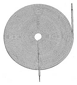
More about flat spiral coils
A flat spiral coil is a type of an air core inductor
usually incorporated in the primary of a tesla generator,
RFID tag, and proximity detectors. In the same category
as the flat spiral coils we have planar spiral coils,
planar square spiral coils, planar rectangular spiral
coils, planar hexagonal spiral coils and octagonal spiral
coil. Planar coils are mostly used in high frequency
applications and designed as tracks on a circuit board.
A flat spiral coil belongs to the category of air core inductors
An “air core inductor” is an inductor that does not depend upon a ferromagnetic material to achieve its specified inductance. Some inductors are wound without a bobbin and just air as the core. Some others are wound on a bobbin made of bakelite, platsic, ceramic etc.
Advantages of an air core coil:
Its inductance is unaffected by the current it carries.
This contrasts with the situation with coils using ferromagnetic cores whose inductance tends to reach a peak at moderate field strengths before dropping towards zero as saturation approaches. Sometimes non-linearity in the magnetization curve can be tolerated; for example in switching power supplies and in some switching topologies this is an advantage.
In circuits such as audio cross over filters in hi-fi speaker systems you must avoid distortion; then an air coil is a good choice. Most radio transmitters rely on air coils to prevent the production of harmonics.
Air coils are also free of the “iron losses” which a problem with ferromagnetic cores. As frequency is increased this advantage becomes progressively more important. You obtain better Q-factor, greater efficiency, greater power handling, and less distortion.
Lastly, air coils can be designed to perform at frequencies as high as 1 Ghz. Most ferromagnetic cores tend to be rather lossy above 100 MHz.
And the “downside”:
Without a high permeability core you must have more and/or larger turns to achieve a given inductance value. More turns means larger coils, lower self-resonance dur to higher interwinding capacitance and higher copper loss. At higher frequencies you generally don’t need high inductance, so this is then less of a problem.
Greater stray field radiation and pickup:
With the closed magnetic paths used in cored inductors radiation is much less serious. As the diameter increases towards a wavelength (lambda = c / f), loss due to electromagnetic radiation will become significant. You may be able to reduce this problem by enclosing the coil in a screen, or by mounting it at right angles to other coils it may be coupling with.
You may be using an air cored coil not because you require a circuit element with a specific inductance per se but because your coil is used as a proximity sensor, loop antenna, induction heater, Tesla coil, electromagnet, magnetometer head, or deflection yoke etc. Then an external radiated field may be what you want.
 Circuits.dk Something about electronics circuits


